RevolutionSyncSampling (FPScript)
Transforms a signal sampled over time into the revolution domain, i.e. the time signal is transformed into an equidistantly sampled rotational speed range by resampling. Effective method for performing order tracking, since the frequency spectrum of the signal converted to the revolution domain directly provides the order spectrum. In the same way, ordinary bandpass filtering in the revolution domain can be used to calculate the (temporal) order curves directly.
Syntax
RevolutionSyncSampling(Signal, Speed, [ SamplesPerRevolution = 0 ], [ SamplesPerRevolutionLimit = 256 ], [ ResampleMethod = REVSYNCSAMPLING_RESAMPLE_LINEAR ], [ ResampleFactor = 2 ] [ , OutputOptions = REVSYNCSAMPLING_OUTPUT_SIGNAL ])
The syntax of the RevolutionSyncSampling function consists of the following parts:
Part |
Description |
||||||||||
|---|---|---|---|---|---|---|---|---|---|---|---|
Signal |
The signal sampled over time, which is to be transformed into the equidistant revolution domain. The unit of the X component must be compatible with the seconds unit (with Unit Monitoring switched on). If no unit of the X component is specified or Unit Monitoring is switched off, the unit is always interpreted in seconds. Permitted data structures are signal. All real data types are permitted, except Boolean value, calendar time und time span. Void values are not permitted in this argument. For the X component additional restrictions do apply.The values must be monotonously increasing. Void values are not permitted in this argument. If the argument is a list, then the first element in the list is taken. If this is also a list, then the process is repeated. |
||||||||||
Speed |
The speed signal sampled over time, from which the revolution domain is derived. The unit of the Y component must be compatible to the unit 1/min (or to RPM = revolutions per minute) (with Unit Monitoring switched on). If no unit of the Y component is specified or Unit Monitoring is switched off, the unit is always interpreted as 1/min. The unit of the X component must be compatible with the seconds unit (with Unit Monitoring switched on). If no unit of the X component is specified or Unit Monitoring is switched off, the unit is always interpreted in seconds. The sampling rate does not necessarily have to match the sampling rate of Signal. If it is a scalar value, then it is assumed that the signal to be transformed was recorded at a constant speed. Permitted data structures are scalar value und signal. All real data types are permitted, except Boolean value, calendar time und time span. The argument is transformed to the unit min^-1. Void values are not permitted in this argument. For the X component additional restrictions do apply.The values must be monotonously increasing. Void values are not permitted in this argument. If the argument is a list, then the first element in the list is taken. If this is also a list, then the process is repeated. |
||||||||||
SamplesPerRevolution |
Determines the sampling of the signal transformed into the revolution domain (number of data points per revolution). Half of the value determines the maximum order that can even be calculated using Fourier analysis according to the sampling theorem. A value should be set so that above half the value all other orders are negligible. Otherwise, aliasing occurs (according to the sampling theorem). The default value 0 selects an automatic value so that the theoretically largest order occurring in the signal can still be calculated using Fourier analysis in the order spectrum. To limit the resulting data set size, the automatically calculated value is limited by SamplesPerRevolutionLimit. Permitted data structures are scalar value. All integral data types are permitted. The value must be greater or equal to 0. If the argument is a list, then the first element in the list is taken. If this is also a list, then the process is repeated. If this argument is omitted, it will be set to the default value 0. |
||||||||||
SamplesPerRevolutionLimit |
Upper limit for the automatic calculation of SamplesPerRevolution. A value should be set so that above half the value all other orders are negligible. Otherwise, aliasing occurs (according to the sampling theorem). The argument is ignored if SamplesPerRevolution is not calculated automatically, i.e. if for SamplesPerRevolution a value greater than 0 was selected. Permitted data structures are scalar value. All integral data types are permitted. The value must be greater than 0. If the argument is a list, then the first element in the list is taken. If this is also a list, then the process is repeated. If this argument is omitted, it will be set to the default value 256. |
||||||||||
ResampleMethod |
Specifies the resampling method used to evaluate the time signal at the (non-equidistant) time points of the equidistant revolution sampling points before transformation into the revolution domain. The argument ResampleMethod can have the following values:
If the argument is a list, then the first element in the list is taken. If this is also a list, then the process is repeated. If this argument is omitted, it will be set to the default value REVSYNCSAMPLING_RESAMPLE_LINEAR. |
||||||||||
ResampleFactor |
Specifies the factor by which the sampling rate of the time signal for the resampling methods REVSYNCSAMPLING_RESAMPLE_SPLINE and REVSYNCSAMPLING_RESAMPLE_FFT is increased. The argument continues to be ignored if REVSYNCSAMPLING_RESAMPLE_LINEAR was selected as the resampling method. Permitted data structures are scalar value. All integral data types are permitted. The value must be greater or equal to 2. If the argument is a list, then the first element in the list is taken. If this is also a list, then the process is repeated. If this argument is omitted, it will be set to the default value 2. |
||||||||||
OutputOptions |
Specifies which results are to be returned. Multiple results are output as a list. If, for example, the signal transformed into the revolution domain as well as the time points calculated for the revolution sampling points are to be output, the argument must contain the value REVSYNCSAMPLING_OUTPUT_SIGNAL + REVSYNCSAMPLING_OUTPUT_TIME. The argument OutputOptions can have the following values:
If this argument is omitted, it will be set to the default value REVSYNCSAMPLING_OUTPUT_SIGNAL. |
Remarks
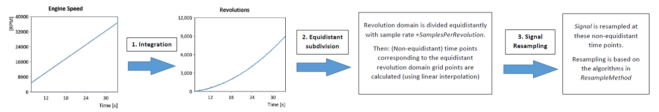
The algorithm of the transformation process can be described schematically as follows:
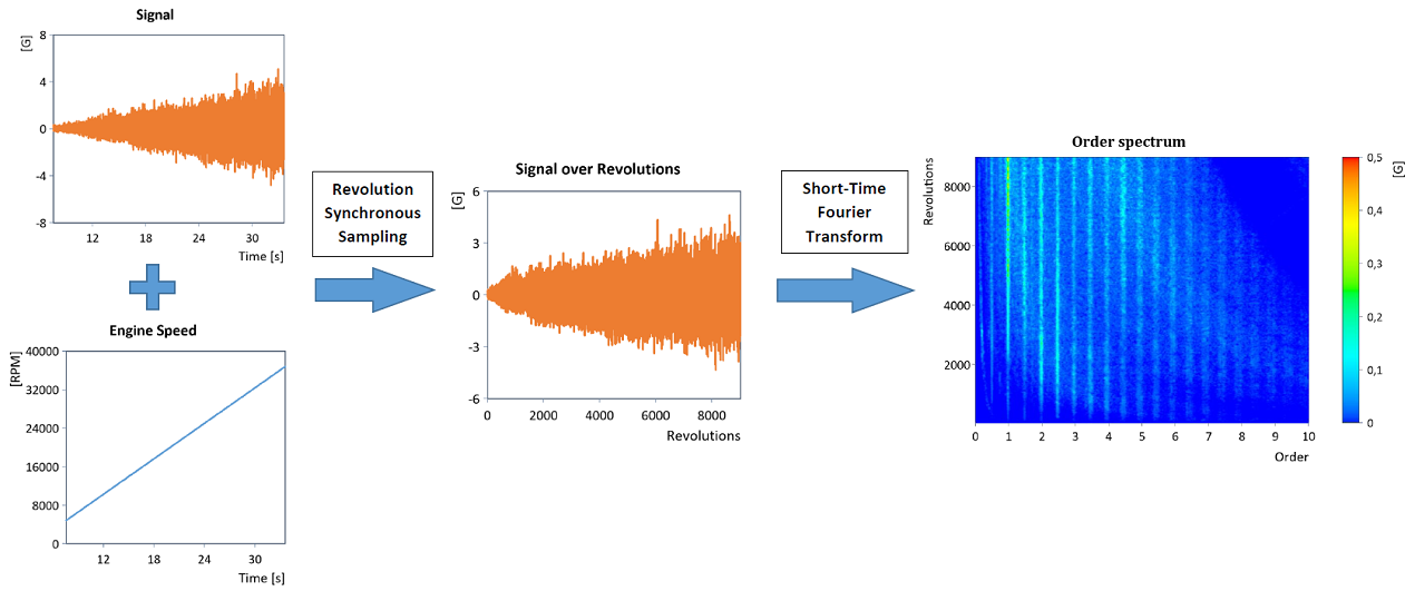
In the literature, the method is also referred to as Synchronous Angular Sampling, Computed Order Tracking, Synchronous Sampling or Adaptive Resampling; see [1], [2], [3], [4], [5] and [6]. It is an effective method for performing order tracking, since the ordinary (time) frequency spectrum of the signal converted to the revolution domain now directly provides the order spectrum:
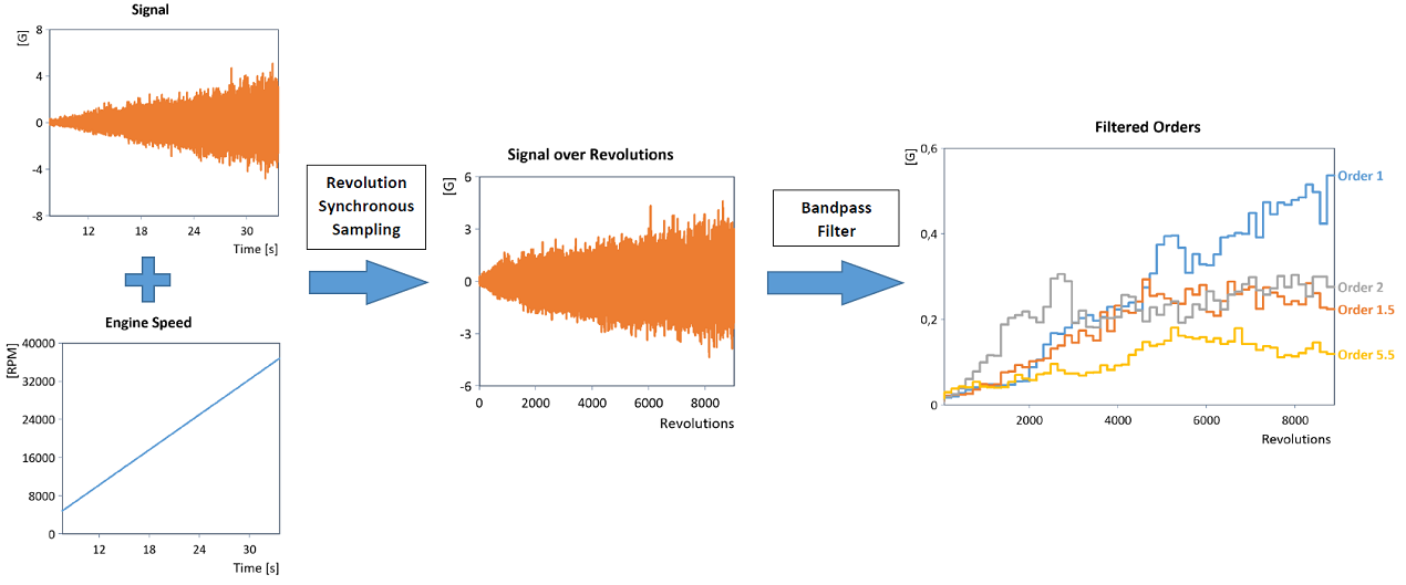
In the same way, ordinary bandpass filtering (e.g. using a suitable IIR bandpass filter) can be used to determine the curve of individual orders in the revolution domain directly (shown here is the blockwise RMS curve of the filtered orders):
Note: Order tracking using revolution synchronous resampling is very flexible and can also be performed for noisy as well as non-monotonic speed data sets.
The results can be accessed using the following list element names:
Constant |
Description |
|---|---|
.["Signal_over_Revolutions"] |
The signal transformed into the revolution domain. |
.["Speed_over_Revolutions"] |
The speed signal transformed into the revolution domain. |
.["Time_over_Revolutions"] |
The (non-equidistant) time points associated with the revolution sampling points. |
You can also always select the Formulaname.Listelementname.
Note According to the sampling theorem, theoretically all orders up to orderMax = 0.5*SamplingRate(Signal)/Maximum(Speed) can be detected and analyzed. So if SamplesPerRevolution is calculated automatically, this value is set to a value greater than twice the value of orderMax. This ensures that all orders up to orderMax are in fact calculated by means of Fourier analysis in the order spectrum and thus aliasing can be avoided as much as possible.
Available in
Option Order Tracking
Examples
RevolutionSyncSampling(Signal, Speed)
Transforms a time-based signal into the revolution domain.
Dim samplesPerRevolution = 64
Dim sigOverRev = RevolutionSyncSampling(Signal, Speed, samplesPerRevolution)
STFTSpectrum(sigOverRev, SPECTRUM_RMSAMPLITUDE,,, 8*samplesPerRevolution,,, 0)
Calculates the order spectrum of the speed-synchronously sampled signal using the time-frequency spectrum (STFTSpectrum function). The order spectrum is calculated up to order 32 (= samplesPerRevolution/2) and has an order resolution of 1/8. Note: If the original signal contained orders of a magnitude greater than 32, these would distort the order spectrum. Alias effects are the result.
Dim sigOverRev = RevolutionSyncSampling(Signal, Speed, 0, 256)
STFTSpectrum(sigOverRev, SPECTRUM_RMSAMPLITUDE,,, 16*SamplingRate(sigOverRev),,, 0)
Calculates the order spectrum of the speed-synchronously sampled signal with order resolution of 1/16. The number of data points per revolution is calculated automatically (but is limited by 256). The theoretically largest order occurring in the signal can therefore still be calculated in the subsequent Fourier analysis.
Dim samplesPerRevolution = 64
Dim sigOverRev = RevolutionSyncSampling(Signal, Speed, samplesPerRevolution)
Dim coeff = IIRPeakFilter(3, 0.5, samplesPerRevolution) // order = 3, bandwidth = 0.5
Dim filteredOrder = Filter(sigOverRev, coeff, TRUE)
Sample(filteredOrder, Signal.X)
Calculates the time curve of the third order (e.g. for acoustic analyses). The filtered third order is calculated with the help of an ordinary IIR bandpass filter in the revolution domain with a band center frequency of 3 and a (symmetrical) order bandwidth of 0.5. It is then transformed back to the original time base.
Dim samplesPerRevolution = 64
Dim sigOverRev = RevolutionSyncSampling(Signal, Speed, samplesPerRevolution)
Dim coeff = IIRPeakFilter(3, 0.5, samplesPerRevolution) // order = 3, bandwidth = 0.5
Dim filteredOrder = Filter(sigOverRev, coeff, TRUE)
XOffsetScale(Mean(filteredOrder, MEAN_SQUARE + CALC_BLOCK, 128 * samplesPerRevolution)[0,-2], 128/2.)
Calculates the blockwise RMS curve of the third order of the speed-synchronously sampled signal (block size = 128 revolutions). The filtered third order is calculated with the help of an ordinary IIR bandpass filter in the revolution domain with a band center frequency of 3 and a (symmetrical) order bandwidth of 0.5.
RevolutionSyncSampling(Signal, Speed,,,,, REVSYNCSAMPLING_OUTPUT_SIGNAL + REVSYNCSAMPLING_OUTPUT_TIME)
Returns the signal transformed into the revolution domain as well as the time points associated with the revolutions.
Dim rev = ChangeUnit(Integral(Speed), "1") // Step 1
Dim rev_equid = (rev[-1]*128, 0, 1/128) // Step 2
Dim t_nonequid = Sample(rev.X, rev.Y, rev_equid, true)
Dim sig = Sample(Signal, t_nonequid, true) // Step 3
Signal(sig, rev_equid)
Equivalent FPScript code for RevolutionSyncResampling(Signal, Speed, 128,, REVSYNCSAMPLING_RESAMPLE_LINEAR).
Dim rev = ChangeUnit(Integral(Speed), "1") // Step 1
Dim rev_equid = (rev[-1]*128, 0, 1/128) // Step 2
Dim t_nonequid = Sample(rev.X, rev.Y, rev_equid, true)
Dim sig = Sample(Resample(Signal, 4, RESAMPLE_FFT), t_nonequid, true) // Step 3
Signal(sig, rev_equid)
Equivalent FPScript code for RevolutionSyncResampling(Signal, Speed, 128,, REVSYNCSAMPLING_RESAMPLE_FFT, 4).
See Also
HarmonicRemovalFilter Function
Revolution Synchronous Sampling Analysis Object
Revolution Synchronous Order Tracking Analysis Object
Time-Frequency Spectral Analysis - Analysis Object
References
[1] K. R. Fyfe, E. D. S. Munck: Analysis of computed order tracking. In: Mechanical Systems and Signal Processing, Vol. 11, Issue 2, Pages 187-205. 1997.
[2] Jürgen Helmut Funck: Synchronous data acquisition with wireless sensor networks. In: Chichester, UK: John Wiley and Sons. 2011.
[3] Bonnardot, F. et al.: Use of the acceleration signal of a gearbox in order to perform angular resampling (with limited speed fluctuation). In: Mechanical Systems and Signal Processing, Vol. 19, Issue 4, Pages 766-785. 2005.
[4] J. Blough: Adaptive Resampling - Transforming from the time to the Angle domain. In: 24th Conference and Exposition on Structural Dynamics, IMAC-XXIV. 2006.
[5] J. Blough: A survey of DSP methods for rotating machinery analysis, what is needed, what is available. In: Journal of Sound and Vibration, Vol. 262, Issue 3, Pages 707-720. 2003.
[6] A. Brandt: Noise and Vibration Analysis: Signal Analysis and Experimental Procedures. In: John Wiley and Sons, Ltd., Chichester. 2011.