Harmonic Filter Analysis Object (Order Tracking Option)
The Harmonic Filter analysis object removes or extracts harmonic components of a selected order from time signals. To do this, the data is converted from the time domain to the revolution domain, where cycle averaging and subtraction provides the desired harmonic removal (details on the algorithm can be found under the HarmonicRemovalFilter function).
As an example, consider the order spectrum of a time signal calculated from a run-up:
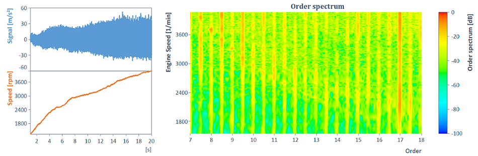
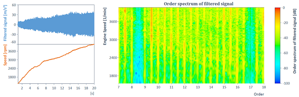
Using the Harmonic Filter analysis object, order 8.5, for example, can be removed together with all harmonic components:
Data tab
This tab specifies the input data in the time domain (from which harmonic components are to be removed or extracted):
Signal in the timedomain
The data structure of the time signal to be filtered for the analysis object must be Signal. The Speed can be specified in the Signal data structure (corresponds to run-up or variable speed) or as a scalar value (corresponds to constant speed or fundamental frequency).
If there are no units or unit management is switched off, the speed is always interpreted in the unit [1/min] and the X component of the time signal is interpreted in the unit .
The instantaneous speed is often measured with a pulse encoder, which records a certain number of pulses per revolution. You can convert the resulting pulse signal directly into a speed signal. To do this, select the option Speed is pulse signal and specify the Number of pulses per revolution. The conversion of the pulse signal into a speed signal is done with the ImpulseToFrequency function.
Options tab
The settings and parameters for harmonic filtering are defined in this tab.
Output
The following two output modes are available:
Mode |
Description |
|---|---|
Filtered time signal without harmonic components |
The time signal is returned without harmonic components of the order to be filtered. |
Harmonic components of the time signal extracted |
Only the harmonic components of the order to be filtered are extracted and returned as a time signal. |
Algorithm settings (revolution domain)
For harmonic filtering, the time signal is first transformed to the revolution domain, where moving cycle averaging and subtraction is performed. The Number of cycles to be averaged in the revolution domain (to calculate the respective averaged harmonic order can be specified explicitly. The larger the value, the greater the filter selectivity.
In addition, the Number of data points per revolution for the signal transformed into the revolution domain is specified. This determines the sampling of the transformed signal in the revolution domain. Half of the value determines the maximum order that can even be calculated using Fourier analysis according to the sampling theorem. A value should therefore be chosen so that all orders above half of that value are negligibly small. Otherwise, aliasing occurs (according to the sampling theorem). Smaller values, on the other hand, reduce the algorithm calculation time. The value must also be divisible by the order to be filtered. If the latter condition is not met, approximated values for the number of data points per revolution and the order to be filtered are automatically calculated and used (for more information, see the HarmonicRemovalFilter function).
Examples
In the project database C:\Users\Public\Documents\Weisang\FlexPro\2021\Examples\OrderT racking Analysis.fpd or C:>Users>Public>Public Documents>Weisang>FlexPro>2021\Examples\Order Tracking Analysis.fpd you will find examples of the different use cases and modes for which an order analysis can be performed. In particular, the diagrams above are included there.
FPScript Functions Used
See Also
Revolution Synchronous Order Tracking Analysis Object