Shock Response Spectrum Analysis Object and Template (Spectral Analysis Option)
The Shock Response Spectrum (SRS) is computed from the signal of an accelerometer. The acceleration signal is used for primary excitation of a series of single degree of freedom (SDOF) systems with customizable natural frequencies. The spectrum is formed by the absolute maxima, maxima or minima of these systems’ responses. The shock response spectrum was originally introduced to analyze the damage potential of mechanical impulses, but it can also be used to analyze the damage potential of stationary random vibrations.
Model
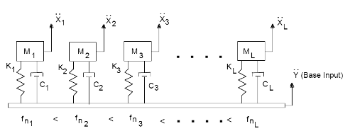
Ϋ ... Input signal
Mi ... Mass of the ith system
Ci ... Damping coefficient of the ith system
Ki ... Stiffness of the ith system
fni ... Natural frequency of the ith system
![]() ... Acceleration response of the ith system
... Acceleration response of the ith system
Algorithm
To calculate the shock response spectrum, a recursive digital filter is used to simulate the SDOF system. The maxima or minima of the response then result in the spectrum.
Result Type
The analysis object can calculate the responses of single degrees of freedom. The result is then a signal series with time in the X component and frequency in the Z component.
Alternatively, you can also directly calculate one or more shock response spectra. If you select several spectra, these are returned as a list.
Result
The responses or the shock response spectra can be calculated for the acceleration, velocity or displacement.
The following then applies:
![]() = a
= a
v = a / (2 * PI * fni)
s = v / (2 * PI * fni)
Frequency
To calculate the shock response spectrum, any natural frequencies can be used. Frequently, however, frequencies are used in a proportional bandwidth, such as 1/6 octave. This means that a frequency corresponds to 21/6 times the previous frequency. In addition to the logarithmic frequency division, a linear frequency division is also available. Here, the spacing between individual frequencies is equal. To calculate the natural frequencies, a starting value and an end value can be specified. Alternatively, the maximum frequency can be determined using the normalized ending frequency (maximum frequency = factor * sampling rate). The factor is not permitted to exceed the value 0.1.
Attenuation
In addition to frequencies, the damping is specified for every SDOF system. The damping applies to all systems and can be determined using the damping ratio ξ or quality factor Q. The damping is frequently adopted with 5% (ξ = 0.05; quality factor Q = 10). The following applies: Q = 1 / (2 * ξ)
Spectrum
You can choose one or more of the following spectra. If you select more than one, the result of the analysis object will be a list:
Spectrum |
Description |
|---|---|
Absolute maxima over total time span |
The absolute maxima are calculated over the total time of SDOF system responses and plotted over the natural frequencies. |
Maxima over total time span |
The maxima are calculated over total time of SDOF system responses. |
Minima over total time span |
The minima are calculated over total time of SDOF system responses. |
Absolute maxima during shock event |
The absolute maxima are calculated during the shock event. |
Maxima during shock event |
The maxima are calculated during the shock event. |
Minima during shock event |
The minima are calculated during the shock event. |
Maxima after shock event |
The absolute maxima are calculated during the shock event. |
Maxima after shock event |
The maxima are calculated after the shock event. |
Minima after shock event |
The minima are calculated after the shock event. |
Starting index and ending index
These two values are used for setting the time signal in the three domains before, during and after the shock event.
You can determine the starting index and ending index using the cursors. To do this, highlight the option Select shock event with cursors in the Analysis Wizard. Now move the two cursors in the lower diagram in order to limit the range. The positions will be adopted as soon as you leave the diagram by using the mouse.
You can also create a shock response spectrum analysis object directly and then set the indices: To do this, create a 2D diagram with the signal to be analyzed. Place the first cursor on the starting position and the second cursor at the ending position. Now click on Insert[Analyses] > Spectral Analysis > Shock Response Spectrum to create an analysis object that calculates a shock response spectrum. The Spectrum is set to Maxima during shock event and the cursor positions are entered into the Starting index and Ending index fields.
References
•Irvine Tom. (2002), "An Introduction To The Shock Response Spectrum".