3D View and Lighting
The 3D view is determined by specifying an angle of inclination and an angle of rotation. Here, the angle of rotation specifies by how many degrees the coordinates system should be rotated clockwise around the Y axis. The angle of inclination determines by how many degrees the coordinates system should be tilted counter-clockwise, relative to the projection plane.
An angle of rotation and an angle of inclination of 0 specify that the viewing angle is located exactly opposite the XY plane of the coordinates system.
The following diagrams are a few examples:
|
|
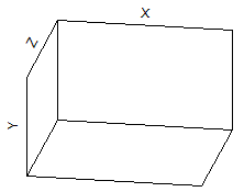
Angle of rotation = Angle of inclination = 0° (opposite the XY plane, Z points to the viewer) |
Angle of rotation = 10°, Angle of inclination = 30° (Standard) |
|
|
Angle of rotation = 0°, Angle of inclination = 90° (plan view, Y points to the viewer) |
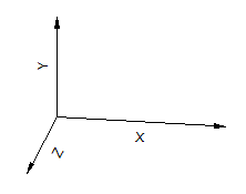
Angle of rotation = 90°, Angle of inclination = 0° (opposite the YZ plane, X points to the viewer) |

The axis system of 3D diagrams can be presented as an axis intercept with planes or as an axis intercept only:
|
|
Axes and planes |
Only axes |
While the planes are always displayed behind the curve, the axis intercept is always displayed in the coordinates origin, even if it ends up in front of the curve.
For curves types with surfaces (surface, columns), you can also add a lighting source. The position of the lighting source is determined similarly to the viewing angle, but here, all of the angle specifications are relative to the viewing angle.